Coiled Tubing Logging Cable Head
Achieve an optimized coiled tubing bottomhole assembly while providing an electrical path for a mono-conductor cable.
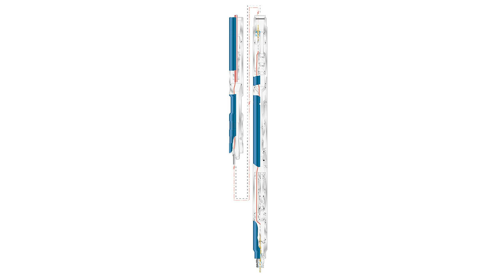
The coiled tubing (CT) cable logging head for mono-conductor cables is a robust tool that integrates six standard NOV products into an optimized assembly. This assembly provides a CT bottomhole assembly (BHA) with the required standard CT safety and disconnect features while also providing an electrical path for a mono-conductor cable. Although the tool is primarily designed for cable logging applications, it can be used for any application in which an electrical connection is required below the tool.
The CT cable logging head can be connected quickly and simply to the coiled tubing using the CARSAC connector. This allows the majority of the tool to be pre-assembled away from the rig floor, providing time savings and improving safety.
The tool consists of a cable anchor sub, coiled tubing quick connect (CARSAC), twin flapper check valve, hydraulic disconnect, circulation control valve, and electrical connectors of choice. It is made from alloy steel and is suitable for mild H2S environments.
The tool can be supplied with a variety of industry-standard CT mono-conductor electrical connectors. Please specify the connection required when ordering.
Cable anchor sub
The cable anchor sub is located at the top end of the assembly and has several functions. It provides a connection to the preinstalled coiled tubing connector while also providing an anchor point for the armored cable. The armored cable is clamped in place using a slip assembly. Once fully installed, the top half of the CARSAC connector can be threaded to the lower end.
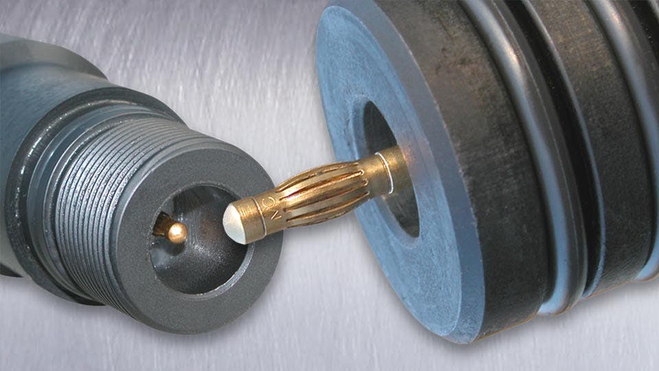
CARSAC joint
The CARSAC connector is a torque-resistant coiled tubing quick connect. It allows for fast and simple connection of the tool or BHA to the coiled tubing. The upper section is attached to the coil by threading to the lower end of the cable anchor sub. The lower section is threaded to the remainder of the cable logging tool.
This provides both time savings and improvements in safety. Time spent on the rig floor attaching the tools to the coil is minimized, and the majority of the cable head assembly can be assembled in a safe, comfortable environment.
Once the top half of the CARSAC is connected to the cable anchor sub and the lower half of the cable head is assembled, the two sections can be mated and secured quickly and easily. The mating process consists of aligning and stabbing the two sections together and then securing them with a double collar. This secures the whole cable head assembly to the coiled tubing.
Twin flapper check valve
The twin flapper check valve with electrical bypass is a high-integrity safety device used to prevent the inflow of fluids into the coiled tubing in the event of failure or damage to the coiled tubing string or surface equipment. It is a one-way valve that allows fluid and drop balls to pass down through the flappers but prevents inflow of fluids and pressure into the coiled tubing. The flappers provide a high-integrity seal and can be supplied with dual seals to provide elastomeric sealing at low pressure and metal-to-metal sealing at high pressures. Dual flappers provide redundancy for additional safety. The flappers are housed in cartridges that can be easily replaced, allowing for simple and quick assembly and disassembly.
The upper part of this assembly houses the primary electrical bulkhead into which the flying lead from the cable anchor sub is passed through the CARSAC and connected to the top of this bulkhead. Below this bulkhead the fluid path and the electrical paths are separated and isolated. The fluid path maintains pressure integrity through the check valves while the electrical path bypasses the check valves without compromising their integrity.
Heavy-duty overpressure release joint
The heavy-duty overpressure (HDOP) release joint is a robust, high-strength assembly used to disconnect the coiled tubing from the tool/work string should it become stuck downhole. When activated, the tool will disconnect in a controlled manner at a predetermined point in the tool. The release joint is designed to withstand vibration and torsional loading and provides an electrical connection through the tool. The release joint is flow activated and leaves an internal fish neck facing upwards after the disconnect. This enables the remainder of the work/tool string left downhole to be easily latched with a standard GS pulling tool. Shear pins ensure that the release joint is not activated accidentally by a pressure surge at the tool.
To release the HDOP release joint, the circulation pump rate is increased to a predetermined level (see circulation control valve section below). An internal piston with varying diameters is exposed to this internal pressure, causing the piston to move down after shearing retaining shear screws. The movement of this piston releases the latching device. To ensure that the tool is not released accidentally by a pressure surge, a secondary overpull on the coiled tubing is required to complete release. This secondary overpull will shear a second set of pins that are preset by the operative to suit the specific operation.
Circulation control valve
The circulation control valve is a standard, robust downhole device that allows fluid circulation to be established through the coiled tubing above the work/tool string. It has two principal functions:
- To provide controlled backpressure on the circulated fluid when working in an underbalanced well operation. The flow rate and backpressure are controlled by changing choke beans in the assembly.
- To provide an adjustable maximum circulation shutoff control valve to enable the HDOP release joint to operate effectively. At a predetermined internal flow pressure, the internal piston of the circulation control will move forward and close the flow path. Internal pressure in the coil will then build to the required release pressure. If the maximum flow rate is reached as a result of a pressure surge, the internal piston will return and open the circulation path. The fluid path exits the coiled tubing assembly at this point into the annular volume. The electrical conduit bypasses the circulation control valve and is terminated at the lower internal bulk head.